Getting Started!
1. Getting Started with JuicyBoard
JuicyBoard is the foundation of a modular, open source platform that makes it easy for you to build a custom 3D printer, CNC router, or any other device driven by stepper motors. JuicyBoard is not pre-populated with any drivers, switches, or other functions, instead, it includes only the components for common core functions (e.g., microcontroller, USB port, SD card, etc.). The user has control over adding the necessary functional modules for the target application. This modular approach gives the platform a number of advantages over static board designs. JuicyBoard runs the open source firmware Juicyware, which is a fork of Smoothieware.
Available modules for the platform are listed here.
2. Quick Look At the Base Board (R1000AX)
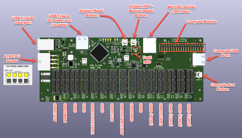
Here are the main features for the R1000AX base board
3. How to Power Up The System
There 2 ways to power the base board
3.1 Application Power Up
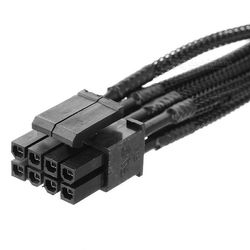
Connect an 8-pin ATX power cable used to power the CPU to the board power input. The socket is keyed so the PCIe power cable will not plug in.
Watch the FAULT LED, which will light RED if the voltage is above 24V or below 9V. In that case the on-board high voltage rail is disabled.
3.2 Data USB Power Input
In some cases where you want to debug the board without connecting the application, JuicyBoard low voltage rails (5V and 3.3V) will be powered through the USB data port. The high voltage rail will be disabled, so stepper motors will not function, but other low voltage logic will function (such as R1008 RTD temperature sensor). This is not recommended for application use.
4. Where Can I Plug Which Modules
JuicyBoard is designed with maximum flexibility in mind. As a general rule ANY module can plugged into ANY socket, considering the following special sockets:
Socket #8 : This socket shares the pins for UART0 which is active by default and acts as a terminal port to the microprocessor. To use the functional pins you have to disable UART0 by adding this line to the config file
uart0_disable true
Socket #11 : This socket shares the pins used to drive the 4 status LEDs. To use the functional pins of this socket you have to disable the LEDs by adding this line to the config file
leds_disable true
Sockets #13, #14, #15 : These sockets share the pins used in Smoothieboard v1 to drive the ethernet port. To use these sockets you must make sure that networking is disabled by adding this line to the config file
network.enable false
5. Getting Started With Modules
All modules share some common features, they use I2C0 bus for configuration and data transfer (that's why I2C0 is accessible to the user). Some modules (such as R1001 and R1008) come with a tiny on board microcontroller.
5.1 Hard Resetting the Modules
For any reason if you need to reset the modules you can push the ISP button shown in the board image above. You can also reset the modules bu running the following command in the console:
mod reset
NOTE: when modules reset they will enter into BOOTLOADER mode and they lose all their configuration values loaded from the config file. You MUST activate every module to restore functionality by running:
mod activate [#]
where [#] in this case must be replaced by the socket number.
It is highly recommended to reboot JuicyBoard to activate modules and reload proper configuration
5.2 Scanning for Modules
You can scan for populated modules using the following command:
mod scan
ONLY smart modules (R1001 and R1008) will respond to this command.
Here's an example, mod scan can output something like
Scanning I2C bus ...
Slot 1 NO CARD, ID: -1
Slot 2 NO CARD, ID: -1
Slot 3 NO CARD, ID: -1
Slot 4 MOD #0x1, FW 0x1, PLATID 0x1
Slot 5 MOD #0x1, FW 0x1, PLATID 0x1
Slot 6 MOD #0x1, FW 0x1, PLATID 0x1
Slot 7 NO CARD, ID: -1
Slot 8 NO CARD, ID: -1
Slot 9 MOD #0x8, FW 0x1, PLATID 0x1
Slot 10 NO CARD, ID: -1
Slot 11 NO CARD, ID: -1
Slot 12 NO CARD, ID: -1
Slot 13 NO CARD, ID: -1
Slot 14 NO CARD, ID: -1
Slot 15 NO CARD, ID: -1
That means slots #4,5,6 are populated with R1001 (#0x1) and slot #9 is populated with R1008 (#0x8). Rest of the slots are not populated with smart cards.
If you get something like
Scanning I2C bus ...
Slot 1 NO CARD, ID: -1
Slot 2 NO CARD, ID: -1
Slot 3 NO CARD, ID: -1
Slot 4 MOD #0xfe, FW 0xfe, PLATID 0xfe
Slot 5 MOD #0xfe, FW 0xfe, PLATID 0xfe
Slot 6 MOD #0xfe, FW 0xfe, PLATID 0xfe
Slot 7 NO CARD, ID: -1
Slot 8 NO CARD, ID: -1
Slot 9 MOD #0xfe, FW 0xfe, PLATID 0xfe
Slot 10 NO CARD, ID: -1
Slot 11 NO CARD, ID: -1
Slot 12 NO CARD, ID: -1
Slot 13 NO CARD, ID: -1
Slot 14 NO CARD, ID: -1
Slot 15 NO CARD, ID: -1
That means that slots #4,5,6,9 are populated with smart modules that are in BOOTLOADER mode, this propbably due to a module reset without activating the modules and loading configuration.
6. R1001 Getting Started
R1001 is a smart stepper motor driver, here's a VERY simplified block diagram of R1001
The 8051 MCU performs various functions including current set, power monitoring and acts as a GPIO extender for the main MCU.
R1001 modules can be populated in any slot, given the considerations in section 4 above. You can populate up to 15 stepper motors with independent STEP/DIR control.
It's NOT recommended to hot swap R1001 modules, make sure the system is completely turned off before populating/depopulating modules.
6.1 Using R1001 Modules With Smoothieware Functions
Juicyware includes a few extra configuration switches that facilitates assigning stepper motor functions. Here's an example:
alpha_slot_num                               7
alpha_steps_per_mm                           80
stepmotor_7_stepres                          16
stepmotor_7_current                          1000
stepmotor_7_decay_mode                       fast
alpha_max_rate                               15000.0          # mm/min

beta_slot_num                                6
beta_steps_per_mm                            80
stepmotor_6_stepres                          16
stepmotor_6_current                          1000
stepmotor_6_decay_mode                       fast
beta_max_rate                                15000.0          # mm/min

gamma_slot_num                               5
gamma_steps_per_mm                           80
stepmotor_5_stepres                          16
stepmotor_5_current                          1000
stepmotor_5_decay_mode                       fast
gamma_max_rate                               15000.0          # mm/min

extruder.hotend0.enable                      true             # enable extruder 0
extruder.hotend0.slot_num                    12
stepmotor_12_stepres                         16
stepmotor_12_current                         1000
stepmotor_12_decay_mode                      fast
extruder.hotend0.steps_per_mm                83.17            # Steps per mm for extruder stepper
extruder.hotend0.default_feed_rate           600              # Default rate ( mm/minute ) for moves where only the extruder moves
extruder.hotend0.acceleration                500              # Acceleration for the stepper motor, as of 0.6, arbitrary ratio
extruder.hotend0.max_speed                   50               # mm/s
extruder.hotend0.x_offset                    0                # x offset from origin in mm
extruder.hotend0.y_offset                    0                # y offset from origin in mm
extruder.hotend0.z_offset                    0                # z offset from origin in mm
This part of a delta printer configuration here. Unlike Smoothiware step/dir/en pins don't need to be declared individually, only the slot #. In this example the alpha motor driver is populated in slot #7, with step resolution set to 16 microsteps, motor current is set to 1000mA, decay mode is set to fast (check the DRV8825 datasheet for more info). Similarly the beta motor driver is in slot #6, with 16 microsteps, 1000mA current and fast decay mode.
6.2 Command Line for R1001
There are a few console commands that can read and modify R1001 settings on the fly
mod r1001 [#X] getcurrent`

[#X] : slot number
This command reads the set current in mA.
mod r1001 [#X] setcurrent [#Y]
[#X] : slot number
[#Y] : current value in mA
This command sets the current of the target R1001 module to #Y in mA.mod r1001 [#X] getres
[#X] : slot number
This command reads microstepping setting.mod r1001 [#X] setres [#Y]
[#X] : slot number
[#Y] : target microstepping resolution
This command sets microstepping resolution to 2^#Y, always a power of 2.
If #Y=4 microstepping resolution is set to 1/16.mod r1001 [#X] getmctl
[#X] : slot number
This command reads the MCTL control registerFor MCTL and other registers see here.
mod r1001 [#X] dreset

[#X] : slot number
Resets the DRV8825 chip
mod r1001 [#X] decayfast
[#X] : slot number
Sets DRV8825 decay mode to FASTmod r1001 [#X] decayslow
[#X] : slot number
Sets DRV8825 decay mode to SLOWmod r1001 [#X] decaymixed
[#X] : slot number
Sets DRV8825 decay mode to MIXEDmod r1001 [#X] getmstat
[#X] : slot number
Reads MSTAT registerFor MSTAT and other registers see here.
6.3 Dumping and Loading R1001 Embedded Firmware
These commands can be used to read or update the firmware of the embedded EFM8 MCU on R1001 modules. They also apply to R1008 modules.
mod dumphex [#]

[#] : slot number
This command dumps the entire flash memory of the embedded EFM8 MCU (including the bootloader code)
mod wrhex2bl [#] [FileName]
[#] : slot number
[FileName] : file name (full path in SD card)
This command writes the given hex file to the R1001 embedded EF8 MCU, MUST BE IN BOOTLOADER MODE
FileName should look like /sd/r1001.hexmod chkfwsig [#]
[#] : slot number
This command the firmware signature of R1001 embedded EF8 MCU, important for integrity checks7. R1002, R1003, R1007 Getting Started
Nothing special needed, just hook the modules and assign the corresponding pins exactly the same way you would do in Smoothieboard. The mapping for which pin goes to which MCU I/O is in the slot distribution and pin assignment.
R1007 normally comes with a R1005 + ribbon cable. Ribbon cable is keyed. For R1007 you MUST hook an external power supply in the noted connector, this board includes 4x 20A switches (current is limited by the connectors, FETs are rated @ 100A with 1.2mOhm resistance)
8. R1008 Getting Started
R1008 is a dual channel, smart platinum RTD temperature sensor module. It only uses I2C interface for operation so it can be populated on any slot without restrictions (you don't need to disable LEDs, UART0 or ENET as in section 4)
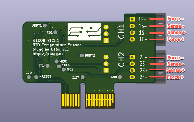
This diagram shows how to hook the RTD element to R1008
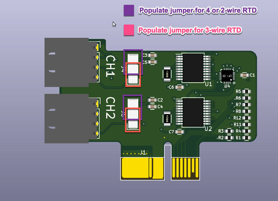
This diagram shows how to place jumpers to select between 3-wire or 2/4-wire RTD measurements.
For more information take a look at the MAX31865 datasheet.
8.1 Using R1008 for Hotend and Heated Bed Temperature Sensing
Juicyware includes a config modifications to facilitate using R1008 temperature sensors for 3D printer hotend and heated beds, here's an example
temperature_control.hotend0.enable            true            # Whether to activate this ( "hotend" ) module at all.
                                                              # All configuration is ignored if false.
temperature_control.hotend0.sensor            r1008
temperature_control.hotend0.slot              3
temperature_control.hotend0.channel           1

....

temperature_control.bed.sensor               r1008
temperature_control.bed.slot                 3
temperature_control.bed.channel              2
In this example the first hotend is configured as r1008 type, with R1008 module populate in slot #3, using channel #1. The heated bed uses channel #2 of the same module, for Juicyware config examples look here.
8.2 Command Line for R1008
Firmware manipulate for the embedded EF8 MCU can be manipulated similar to R1001, look at section #6.3. Using the console you can read the temperature using the following command
mod readrtd [#]

[#] : slot number
This command returns the temperature measured by RTD
elements connected to the given R1008 module


