| Table of Contents |
|---|
...
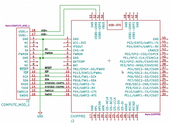
R1100 - C.H.I.P. Pro Interposer
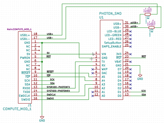
R1101 - particle.io photon Interposer
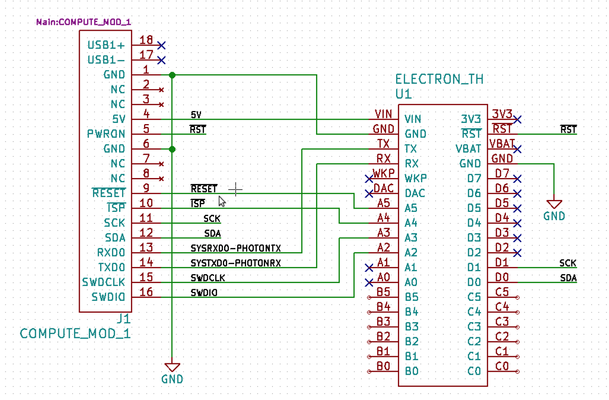
R1102 - particle.io electron Interposer
R1000AX Compute Module Pinout
The table shows the pin description and how they're connected to different modules
| Pin | Description | R1100 C.H.I.P. Pro | R1101 Photon | R1102 Electron |
|---|---|---|---|---|
| SWDIO | LPC1769 Single wire debug IO | PD5 (16) | A2 (10) | A2 |
| SWDCLK | LPC1769 Single wire debug clock | PD4 (15) | A3 (9) | A3 |
| P0[2]-TXD0 | LPC1769 UART0 transmitter, connect to compute module receiver | PD3 (14) | RX (4) | RX |
| P0[2]-RXD0 | LPC1769 UART0 receiver, connect to compute module transmitter | PD2 (13) | TX (3) | TX |
| SDA | I2C Data | PB16 (12) | D0 (13) | D0 |
| SCK | I2C Clock | PB15 (11) | D1 (14) | D1 |
| #ISP | LPC1769 In system programming - places LPC1769 into manufacturer bootloader mode when forced low during reset | PG13 (10) | A4 (8) | A4 |
| #RESET | LPC1769 reset pin | PB2 (9) | A5 (7) | A5 |
| NC | Not connected | - | - | - |
| NC | Not connected | - | - | - |
| GND | Ground | GND (1,6) | GND (2) | GND |
| PWRON | Compute module button, has different functions for different modules | PWRON (5) | #RST (13) | #RST |
| 5V | Compute module 5V supply | CHG-IN (4) | VIN (1) | VIN |
| NC | Not connected | - | - | - |
| NC | Not connected | - | - | - |
| GND | Ground | GND (1,6) | GND (2) | GND |
| USB1- | LPC1769 USB port D- | USB0-UDM0 (52) | USB- (30)[1] | - |
| USB1+ | LPC1769 USB port D+ | USB0-UDP0 (51) | USB+ (31)[1] | - |
[1] pin is connected through a resistor option, the photon microcontroller has the capability for a host/OTG/slave USB
R1100 - C.H.I.P. Pro Interposer Schematic
R1101 - particle.io photon Interposer Schematic
R1102 - particle.io electron Interposer Schematic